RS232#
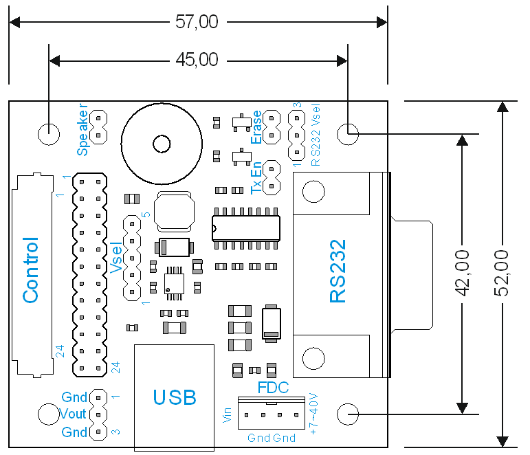
DPA-PCBRS232-2x is an interface board for connecting a color iLCD panel with 20/24-pin FFC cable to the USB port or RS232 port. Input voltage can be 5V or 7 - 40V with an integrated switcher. A mini-speaker for signalling is included.
Connectors and Jumpers#

demmel products RS232 board (DPA-PCBRS232-2x)
Control Connector (Control)#
The DPA-PCBRS232-2x is connected with the iLCD panel via the corresponding FFC cable. Please note, that the 20/24-pin FFC cable enclosed with the DPA-PCBRS232-2x must be inserted with the contact surface upwards as the FFC connector is a top-contact model. The same is true for the FFC connector on the iLCD panel itself. As the board is intended to be used with the parts showing upwards when it is connected with the iLCD panel (display surface showing upwards as well), the FFC cable has the contact surface on the opposite sides on the two ends to accomplish a correct connection between DPA-PCBRS232-2x board and iLCD panel. The DPA-PCBRS232-20 has a 20pin connector and is used for the following displays: DPP-CTS2432, DPP-CTS2440, DPP-CxP3224-2, DPP-CxP3224A, DPP-Cx4827, DPP-Cx3224-2, DPP-Cx6448 The DPA-PCBRS232-24 has a 24pin connector and is used for the following displays: DPP-Cx8048, DPP-Cx1060, DPP-Cx1060A
Speaker on Jumper (Speaker)#
When a jumper is connected to this connector, the Relay 0 output is connected to the DPA-PCBRS232-2x board’s speaker via a resistor.
Transmit Enable Jumper (TxEn)#
When a jumper is connected to this connector, the RS232 transmission to the iLCD panel is enabled.
Erase Jumper (Erase)#
When a jumper is connected to this connector, the iLCD panel erases all user data from the Flash memory at boot time. A corresponding message is shown on the LCD. Please remove the jumper after startup to avoid consecutive erasing of Flash contents at the next startup.
Serial Port Connector (RS232)#
This 9-pin Sub-D female connector allows the driving application or PC to send and receive data from and to the iLCD module via standard RS232 signals. The pinning matches the standard layout of a PC’s serial port. The pins are connected with the iLCD’s serial port 1.
Pin On Sub-D |
Direction |
Description |
|---|---|---|
1 |
- |
RS232 Power In |
6 |
- |
Not connected |
7 |
Out |
RX - data sent from the iLCD module to the controlling application / PC |
3 |
In |
RTS – not in use, but connected to the iLCD’s RS232 driver |
81) |
In |
TX – data sent from the controlling application / PC to the iLCD module |
4 |
Out |
CTS – iLCD’s output for hardware flow control |
9 |
- |
Not connected |
5 |
- |
Not connected |
Note:
See iLCD’s command description about why you should connect this pin and when it is not necessary to use hardware flow control.
USB Connector (USB)#
This connector enables you to connect iLCD’s USB port to a USB port on a PC via a standard USB cable.
Pin |
Direction |
Description |
|---|---|---|
1 |
- |
VCC + 5V |
2 |
In/Out |
USB- |
3 |
In/Out |
USB+ |
4 |
- |
Ground |
Power Supply Configuration Connector (Vsel)#
Only one jumper is allowed to be set to select the power source for the iLCD module as follows:
Jumper connects |
Description |
|---|---|
1 & 2 |
Enables the power supply connector’s pin 4 (VCC) and RS232 if RS232 Vsel is set to 2 and 3 |
2 & 3 |
Enables supplying the iLCD module via the USB port |
3 & 4 |
Enables supplying the iLCD module via the USB port |
4 & 5 |
Enables supplying the iLCD module via the switcher |
Note
Please note, that the DPP-Cx8048, DPP-Cx1060 and DPP-Cx1060A iLCD panels can not be supplied via the USB port, as the USB port allows to draw a maximum of 500 mA only, which is exceeded by the DPP-Cx8048, DPP-Cx1060 and DPP-Cx1060 iLCD panels. Trying to draw more than 500 mA from a USB port can damage your PC under worst circumstances! When the Jumper is set to 4 and 5 the iLCD is powered with the onboard switcher. The output of the switcher is 5V. Using it with an iLCD panel with 3/3.3V will damage the iLCD panel!
RS232 Power Configuration Connector (RS232 Vsel)#
Only one jumper is allowed to be set to select the power source for the iLCD module as follows:
Jumper connects |
Description |
|---|---|
1 & 2 |
Enables supplying the iLCD module via the switcher with RS232 Power In |
2 & 3 |
Enables supplying the iLCD module directly with the RS232 Power In, if Vsel is set to 1 and 2 |
Note
Please note, that the DPP-Cx8048, DPP-Cx1060 and DPP-Cx1060A iLCD panels can not be supplied via the USB port, as the USB port allows to draw a maximum of 500 mA only, which is exceeded by the DPP-Cx8048, DPP-Cx1060 and DPP-Cx1060 iLCD panels. Trying to draw more than 500 mA from a USB port can damage your PC under worst circumstances! When the Jumper is set to 4 and 5 the iLCD is powered with the onboard switcher. The output of the switcher is 5V. Using it with an iLCD panel with 3/3.3V will damage the iLCD panel!
Power Supply Connector (FDC)#
This connector applies the 5V power supply to the iLCD module if there is no USB port connected to the module. The connector used for this connection is the same as the power supply connector for a 3 ½” floppy disk drive, and has the same pinning.
Note
Please note, that all iLCD panels mentioned in this document are available in a 3/3.3V variant optionally as well. If you connect an iLCD panel with 3/3.3V supply to the DPA-PCBRS232-2x, you must use 3/3.3V instead of the 5V supply, otherwise the iLCD panel would be damaged! Supplying the board plus the iLCD panel via USB port is not possible in this case!
Pin |
Description |
|---|---|
+7~40V |
Connected to the switcher via RS232 Vsel, can be +7 ~ +40V |
GND |
Ground |
GND |
Ground |
Vin |
VCC (+5V / +3/3.3V) |
Power Out Connector (Vout)#
Can power the iLCDs DPP-Cx6448 (V2 and newer), DPP-Cx8048, DPP-Cx1060 and DPP-Cx1060A with the 3 pin Power connector.
Pin # |
Pin Name |
Direction |
Primary Function Description |
|---|---|---|---|
1 |
GND |
- |
Ground pin |
2 |
VCC |
- |
5V |
3 |
GND |
- |
Ground pin |
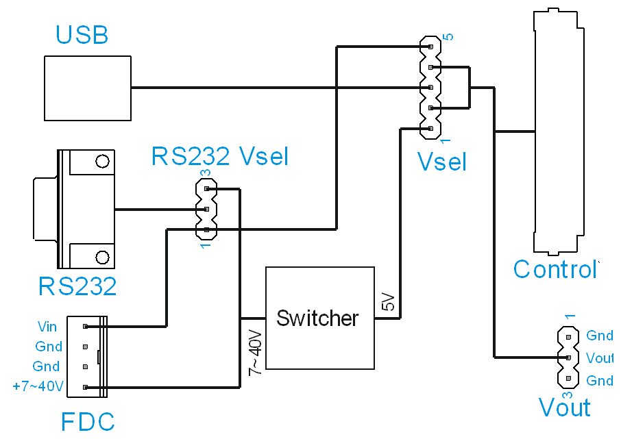
Power Supply#
The following block diagram shows the various ways to supply the display.

demmel products RS232 schematic (DPA-PCBRS232-2x)
Supply via |
Voltage Input |
RS232 Vsel position |
Vsel position |
Voltage output (Control/Vout) |
|---|---|---|---|---|
USB |
5V |
- |
2-3 or 3-4 |
5V |
RS232 |
3.3V |
1-2 |
4-5 |
3.3V |
RS232 |
5V |
1-2 |
4-5 |
5V |
RS232 |
7~40V |
2-3 |
1-2 |
5V |
FDC Vin |
3.3V |
- |
4-5 |
3.3V |
FDC Vin |
5V |
- |
4-5 |
5V |
FDC +7~40V |
7~40V |
- |
1-2 |
5V |
3D Model#
Downloads#